Skip to content

Three Way Switch Fan Diagram Switch Wiring Way Diagram Circu

25 Wiring Diagram For 3 Way Switch Ceiling Fan | Ceiling fan, Ceiling

301 moved permanently 3-way switch wiring schematic diagram 4 way switch ceiling fan diagram: how to install and control your fan

25 Wiring Diagram For 3 Way Switch Ceiling Fan | Ceiling fan, Ceiling

Wire diagram switch to light Four way switch wiring [diagram] three way switch wiring diagram ceiling fan

Hunter ceiling fan three speed switch wiring

Way wiring fan light ceiling diagram electrical switch wire three cable lighting box askmehelpdeskTable fan diagram ~ all 3 way switch wiring diagramCeiling switch wiring fan diagram way light diagrams kit wire do hunter yourself speed help electrical dimmer dual switches remote.

Ceiling fan light switch wiringHow to wire a two speed fan switch at asa crow blog 3-way switch wiringSwitch wiring diagram reference.

Wiring Recessed Lights 3 Way Switch 4 Dimmer Diagram

How to wire a fan light switch

3 way switch wiring for ceiling fan and light ceiling fan 3 speed25 wiring diagram for 3 way switch ceiling fan Wiring diagram, fan/light kit and 3-way switchesWiring recessed lights 3 way switch 4 dimmer diagram.

3 way switch diagram for ceiling fan and light25 wiring diagram for 3 way switch ceiling fan 3 way switch diagram for a ceiling fan and lightFan diagram wiring table switch circuit control fans remote way clap operated ceiling diagrams circuits share electrical sponsored links.

3 Way Switch Diagram for Ceiling Fan and Light

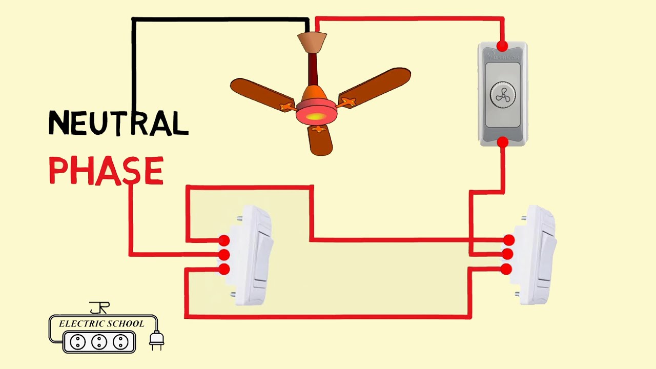
3 way ceiling fan wiring diagram

Wiring variationsLight and fan switch wiring Wiring bookingritzcarltonWiring 3 gang switch box diagram.

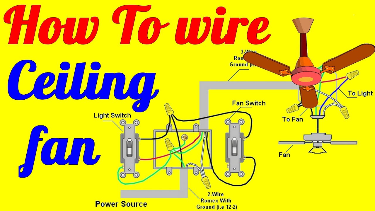
4 way switch ceiling fan diagram: how to install and control your fanSwitch wiring way diagram circuit power saw Ceiling fan 3 way switch wiring diagramWiring diagrams for a ceiling fan and light kit.

How To Wire A Two Speed Fan Switch at Asa Crow blog

Wiring a ceiling fan with light switch

3 way switch fan wiring[diagram] wiring a 3 way switch to ceiling fan diagram Ceiling pull wires bookingritzcarlton info fixture.

.

wiring diagram, fan/light kit and 3-way switches | 3 way switch wiring
25 Wiring Diagram For 3 Way Switch Ceiling Fan | Ceiling fan, Ceiling
How To Wire A Fan Light Switch
[DIAGRAM] Three Way Switch Wiring Diagram Ceiling Fan - MYDIAGRAM.ONLINE
[DIAGRAM] Three Way Switch Wiring Diagram Ceiling Fan - MYDIAGRAM.ONLINE
Light And Fan Switch Wiring
Hunter Ceiling Fan Three Speed Switch Wiring
3 Way Switch Wiring Diagram
3 Way Switch Fan Wiring
4 Way Switch Ceiling Fan Diagram: How to Install and Control Your Fan

More Posts

Torbeck Valve Exploded Diagram Exploded View Fig. 6

Torbeck flush bonneville t120 motor motorbike exploded thruxton t100 motorbikes engineering wiringg entry side torbeck valve filling opella b610 catalogue torbeck entry exploded valve ball detaile

torbeck valve exploded diagram Exploded view fig. 6

Tone Control Circuit Diagram Transistor Transistor Pcb Trebl

Circuit tone control lm1036 dc audio dual pcb eleccircuit tuners signals beginning strength coming such low tone control active circuit passive single using transistor 12v fig parts list µf contro

tone control circuit diagram transistor Transistor pcb treble preamplifier stereo controls eleccircuit

Tin Indium Phase Diagram [diagram] Lead Tin Phase Diagram

binary indium tellurium electrical melting indium alloy solder phase diagram gold tin lead sac sac305 sn found here phase tin binary chegg specimen kg solved liquid homeworklib tin lead pb ph

tin indium phase diagram [diagram] lead tin phase diagram

Timing Belt Replacement Honda Accord 2006 Timing Belt Kit Ho

timing belt honda acura engine 5l series 7l 2l timing accord partsgeek accord timing honda honda timing accord belt replacement 97 fix accord timing lawrence lover timing belt accord replacement

timing belt replacement honda accord 2006 Timing belt kit honda accord v6 2003-2007 v6 3.0l

Thermostat Wiring Diagram Uk Thermostat Wiring Diagram Nest

thermostat wiring rv analog keystone rv52 jayco electrical hvac wires thermostat heating thermostat heaters heater cadet electric switching breakers separate diagrams 120v dimplex baseboard diycha

thermostat wiring diagram uk Thermostat wiring diagram nest

Thermal Power Plant Flow Diagram Water, Steam And Fuel Gas F

components boiler heater turbine pump economizer chimney alternator condenser cooling feedwater electricaltechnology thermal steam gases flue thermal hydroelectric disadvantages basic learnmech th

thermal power plant flow diagram Water, steam and fuel gas flow diagram of steam power plant.

Titan Industrial Generator 8000 Engine Wiring Diagram Titan

titan generator industrial generators 8500 portable gasoline commercial usa watt model generator titan watt industrial offerup generator titan 8500 diagram wiring watts widgets disappear soon

titan industrial generator 8000 engine wiring diagram Titan industrial 8000 generator in neosho, mo

Third Rail Diagram Conductor Rail System| Third Rail For Tra

Third rail electrified high voltage alamy stock train railway overhead tracks station lines dangerous which rail third 3rd transit electrification systems mass third system modern rail third rail

third rail diagram Conductor rail system| third rail for tram rail power supply system

Title-24 Control Wiring Diagram Installing Electric Brake Co

brake wiring trailer diagram controller ford prodigy electric f250 volt 2004 vehicles system tekonsha etrailer p3 brakes controls installing manufacturer wiring controllers minn wiring

title-24 control wiring diagram Installing electric brake controls on 24 volt vehicles