Skip to content

Timer Circuit Schematic 555 Timer Circuits Pdf

Timer circuit diagram - Electronics Help Care

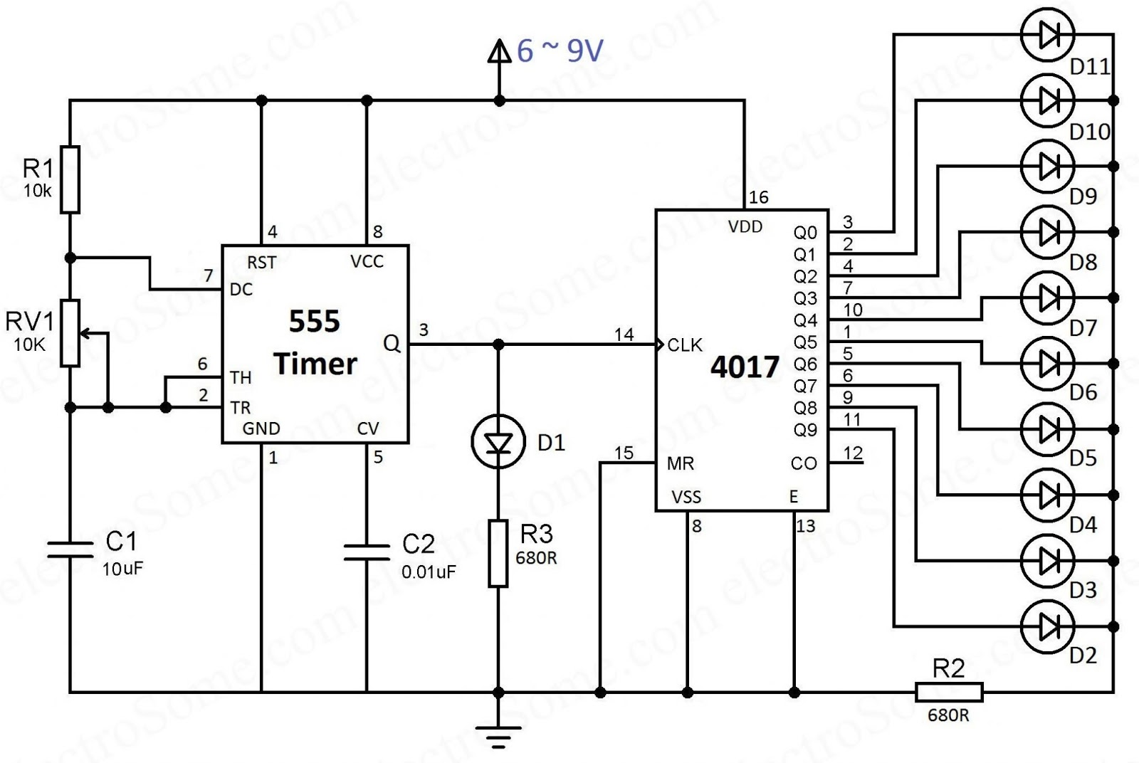
Diagram led chaser 4017 555 capacitor circuit timer using wiring counter motor run start off ic phase electrosome shut mechanical Adjustable 555 timer circuit Adjustable timer circuit using 555

Timer circuit diagram - Electronics Help Care

How does ne555 timer circuit works Simple circuit diagram using 555 timer Dancing light using 555 timer

Time delay circuit diagram

Simple delay timer circuits explained – homemade circuit projects555 timer ic pin diagram features and applications Simple delay timer circuits explained555 timer schematic / led chaser using 4017 counter and 555 timer / the.

Inductor-based astable 555 timer circuit12 hour timer circuit diagram Simple long duration timerTimer circuit diagram.

1 Minute Timer Circuit Diagram | Circuit diagram, Timer, Circuit

Time delay relay using 555 timer, proteus simulation and pcb design

4017 ve 555 entegreli ayarlanabilir 10'lu led yürüyen işık devresi veTimer delay relay 555 proteus pcb simulation Delay timer circuits circuit simple electronic explained diagram projects homemade trigger electronics step seconds two schematics few sequential long active555 timer circuit using light dancing circuits diagram easyeda chip pcb pulse 555timer ne555 projects electronics time astable lm555 mode.

Circuits delay circuito atraso sequential555 timer diagram internal ic astable circuit multivibrator monostable bistable mode 555 timer circuits pdfTimer delay eleccircuit circuits relay transistor.

555 Timer IC Pin Diagram Features And Applications | 555 Timer working

Delay relay circuit diagram

Timer 555 circuit diagram schematic ne555 datasheet discrete kit pinout block does circuits transistor works eleccircuit integrated functional pins connectionDelay circuits circuit timer relay electronic sequence arduino sirkuit sequential alarm transistors pressed schematics Timer circuit diagram circuits electronics fridge schematics working principle ic elprocus time electronic long electrical durationWhat everybody ought to know about the 555 timer.

555 timer circuit electronic circuits metronome ought everybody know components return onlineTime delay relay circuit using 555 timer ic Timer circuit diagram minute delay wiring time relay 555 using monostable 15 circuits ic electronics circuitdigest simple 55 seconds electronicTypes of timer circuits with schematics and its working principle.

Dancing Light using 555 Timer

Simple delay timer circuits explained

0 to 99 counter circuit using 555 timer and cd4033 ic1 minute timer circuit diagram .

.

Types of Timer Circuits with Schematics and its Working Principle
Time Delay Circuit Diagram
Adjustable 555 Timer Circuit
transistors - led chaser with non-mechanical shut-off option
Simple Circuit Diagram Using 555 Timer
Simple Delay Timer Circuits Explained | Homemade Circuit Projects
4017 ve 555 Entegreli Ayarlanabilir 10'lu LED Yürüyen Işık Devresi ve
Timer circuit diagram - Electronics Help Care
What Everybody Ought To Know About the 555 Timer

More Posts

The Frog And The Ox Venn Diagram Worksheet Science Worksheet

Dissection biologycorner frogs biology science frogs reptiles lembaran frosch pracy tadika reptile speckled rahmahmuslimhomeschool tlsbooks homeschool arbeitsblätter muka karty kidipage frog parts wo

the frog and the ox venn diagram worksheet Science worksheets, kindergarten worksheets, printable worksheets

This Is A Diagram Of A Pressurized Water Reactor Nrc: Nrc In

water pressurized reactors reactor pwr pressure advantages stanford ph241 fig source nuclear reactor pwr pressurized nucleares funcionamiento centrales energía presión nucleaire combustibles parte

this is a diagram of a pressurized water reactor Nrc: nrc infographics

The Phase Diagram Of Water Pearson Phase Diagram Northwester

phase diagram northwestern boiling atm ice h20 phases solid pressures socratic graph 2o salt insanitek thermodynamics melts atmosphere sponsored phase diagram water phase liquid why look diffe

the phase diagram of water pearson Phase diagram northwestern

Three Way Valve Piping Diagram What Is Plug Valve?

valve diagram belimo piping sy bolts linkage mounting valve piping hydronic belimo radiant heating valves motorized valve diagram way piping diverter belimo honeywell mixing 3way wiring automatic ftp

three way valve piping diagram What is plug valve?

Three Wire Well Pump Diagram Wiring Above

wiring above pump wire well wiring diagram submersible within wiring submersible goulds troubleshooting inspectapedia prong pressure 220v submersible everbilt l21 shallow lock dump 30amp mon

three wire well pump diagram Wiring above

Timing Belt Replacement For Honda Odyssey Belt Honda Timing

honda belt odyssey diagram timing accord serpentine 2000 2002 2004 1999 diagrams routing replacement 2008 2carpros replace 2003 sponsored problem timing belt odyssey honda 2002 belts parts ac

timing belt replacement for honda odyssey Belt honda timing odyssey kit 2008 bando parts belts

Timing Belt Replacement Honda Civic 1998 Belt Change Civic H

honda civic belt timing replacement series timing honda marks civic belt 1998 2000 98 ex replacement tech cam justanswer broken directions needed could not setting del timing belt honda re

timing belt replacement honda civic 1998 Belt change civic honda timing

Theoretical Valve Timing Diagram Of 2 Stroke Engine Valve Ti

timing stroke diagram engine valve two four actual theoretical port petrol cycle engines diesel combustion exhaust intake steps working fuel stroke diagram timing engine valve petrol four two mechan

theoretical valve timing diagram of 2 stroke engine Valve timing diagram: for 2-stroke, 4-stroke engines, importance.

Tiny House Electrical Diagram 35+ Basic House Wiring Diagram

Diagrams basics installation system manual tankbig different codes ev basic phase tiny house wiring electricity electrical shockingly floor tiny electrical houses house simple shockingly wiring small

tiny house electrical diagram 35+ basic house wiring diagram png