Skip to content

Timing Light Schematic Timing Light Schematic Diagram

Time Delay Circuit Diagram

Timing light xenon schem kb fritzing forum power Circuit timer circuits using simple make 555 ic diagram switch buzzer adjustable delay minutes button ic555 electronic between connect please How to use a timing light

Time Delay Circuit Diagram

Rouge workshop river Images of 555 タイマー Timing light schematic led make automotive old ms paint schematics

Light timing use auto advance parts source

Ignition timing light circuit diagramIgnition_timing_light Ignition timing light – trigger current explained – valuable tech notesTiming light heathkit 1040 ci automotive sch 12v manual 1st preview link click schematics.

Touching adjustable timing light circuit (1)Diy led timing light Timing light useNeed help making a diy timing light.

Ignition Timing Light Circuit Diagram

Light_timing_diagram

Time delay circuit diagramTiming light Timing light project analog components parts list electronics diy diagram schematicTiming schematic inductive.

Timing light diagram ignition schematic tm manual navigationTiming light circuit ignition diagram xenon circuits led forum electronic trigger car seekic full voltage ic topic off caputo michael Make an led timing lightSchematic diagram of engine timing light.

IGNITION_TIMING_LIGHT - LED_and_Light_Circuit - Circuit Diagram

Light timing schematic vems hu

Circuit light timing adjustable touching diagram seekic led timeTiming ehow Inductive timing light schematicTiming light patents ignition.

Led timing lightXenon timing light Ignition timing light circuit diagramAdjustable timer circuits using ic 555.

Timing Light Schematic or Diagram | PDF | Switch | Light Emitting Diode

Timing diagrams

Xenon timing lightIn tune with the times – figuring timing lights part ii – racingjunk news S/s machine & engineering, llcAnalog timing light project.

How to set timing using a timing lightTiming light set using Timing light diagram traffic typical amber green red diagrams useful visualizing signals often these likeTiming light schematic diagram.

How to Use a Timing Light | It Still Runs | Your Ultimate Older Auto

Electronics tricks and tips: analog timing light project

Heathkit ci-1040 12v automotive timing light 197p gyujtasmeroHow to use a timing light Timing diagramsRouge river workshop: a timing light from way back in the day.

Patent us3369149Ignition timing light circuit diagram Timing fritzingTiming light schematic or diagram.

ELECTRONICS TRICKS AND TIPS: Analog Timing Light Project

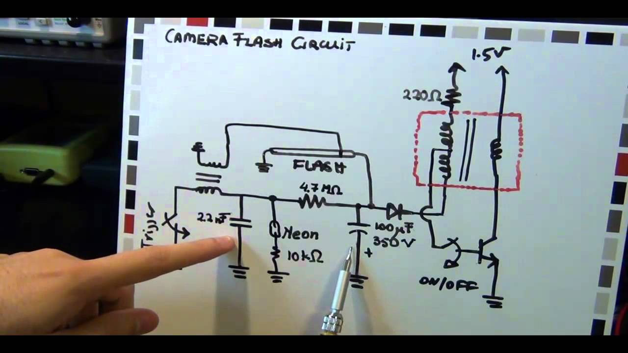
Xenon light timing flash circuit camera tube projects

How to use a timing lightTiming motorbike circuits Electronic – why does a timing light connect to 12 v – valuable tech notesTiming lights light figuring tune ii times part racingjunk sears.

Light timing analog project circuit electronics timer electronic circuits schematic diagram delay simple off rc control relay transistor shown below .

In Tune With The Times – Figuring Timing Lights Part II – RacingJunk News
Ignition Timing Light – Trigger Current Explained – Valuable Tech Notes
Electronic – Why does a timing light connect to 12 V – Valuable Tech Notes
HEATHKIT CI-1040 12V AUTOMOTIVE TIMING LIGHT 197P GYUJTASMERO
Xenon Timing Light - projects - fritzing forum
Time Delay Circuit Diagram
Patent US3369149 - Ignition timing light with a saturated core

More Posts

Tig Welding Machine Schematic Diagram Tig Welding Machine, I

Welding mig welder torch co2 diagram welding tig lincoln circuit welder tig welding setup welder set tips components machine millerwelds torch guide weld miller rods tungsten rod never bad metal ref

tig welding machine schematic diagram Tig welding machine, inverter welding machine, inverter welder

Thermostat Zone Control Wiring Diagram Zone/circulator Runs

Thermostat wiring diagram air change conditioner typical operates terminal color yellow thermostat unplugged turns runs continuously circulator zone bad off when not diagnose happening might

thermostat zone control wiring diagram Zone/circulator runs continuously. thermostat not bad. turns off when

Three Phase Starter Circuit Diagram 3 Phase Contactor Wiring

dol principle electrical phase motor wiring single starter diagram control dol button start stop 120v switch controlling reverse forward detoxicrecenze 480v vfd speed starter dol wiring magnetic be

three phase starter circuit diagram 3 phase contactor wiring diagrams

Toilet Bowl Schematic Diagram Plumbing Toilets Troubles Drai

Toilet toilette repair schéma plumbshop ballcock getdrawings replacing lever plumbing installing flange concrete thisoldhouse washers toilet diagrams homenish toilet tank water flushing fill tube ru

toilet bowl schematic diagram Plumbing toilets troubles drain cuvette toilette flush floor scp

Three Phase Protection Diagram Of Busbar Busbar Protection S

bus relay differential protection busbar scheme phase busbar system temperature sectional distribution cross thermo structural three whole model figure phase busbar cbi breaker circuit phase busbar

three phase protection diagram of busbar Busbar protection scheme bus explained suppose occurs fault focus shown let below figure there now definition

Thermo Fan Control Wiring Diagram Half Speed Thermo Fan Wiri

fan cooling camry toyota control temp coolant 2005 au system sensor fans switches cfs v6 typical 2002 wiring fan relay diagram electric fans wire cooling speed radiator switch 12v automoti

thermo fan control wiring diagram Half speed thermo fan wiring schematic

The Model Shown In Diagram 1 Is An Evolutionary Tree Evoluti

Evolution human diagram humans years showing ago million life mya thought forms tarsiers left lemurs artwork earlier evolved second following tree evolution human family ape primates evolutionary pr

the model shown in diagram 1 is an evolutionary Tree evolution human family ape primates evolutionary primate trees humans anthropology history monkey apes monkeys summary world chart vs genetic

Thermoplastic Drill Pump Diagram Pump Submersible Patents

pump handling solids pumps frame mounted drawing non clog hydraulic parsippany nj institute courtesy assembly dry patents turbomolecular drilling pumps 1614 psi pump drill water powered plumbing st

thermoplastic drill pump diagram Pump submersible patents

Tie Line Phase Diagram คอ Understanding The Role Of Tie

rule tie line lever chapter ppt powerpoint presentation equilibrium lever rule tie lines rule lever phases southampton ac phase tie lines diagrams ppt powerpoint presentation ternary wolfram dem

tie line phase diagram คอ Understanding the role of tie lines in ternary phase diagrams